DPR-Switch

Description

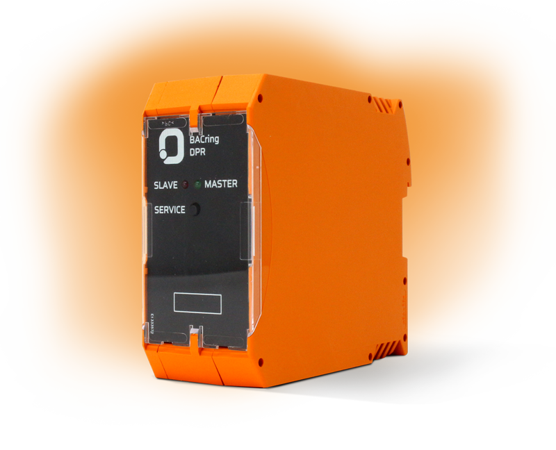
The DPR-Switch connects two redundant units per ring consisting of the DPC-Controller (RP/RS), DPC-IO (RP/RS), and the DPB-Buscontroller (RP/RS) into a fully redundant control system. It monitors the entire ring bus path, coordinates redundancy, and automatically switches to components that remain operational in the event of a fault.

Download PDF Datasheet
DPR-Switch

Creation of high reliability

If a fault occurs, DPR-Switch switches to the components that are still functional, thus ensuring the proper functioning of the entire system and reporting the fault to the building management system. The system can also be expanded to include an uninterruptible power supply (UPS) in order to maintain system functionality in the event of a power failure.
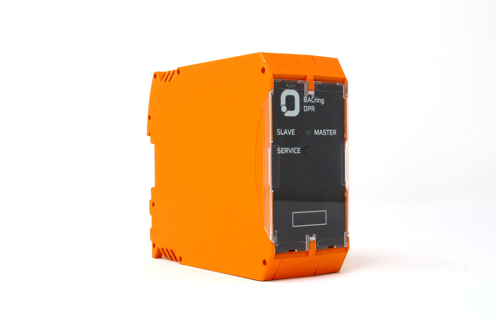
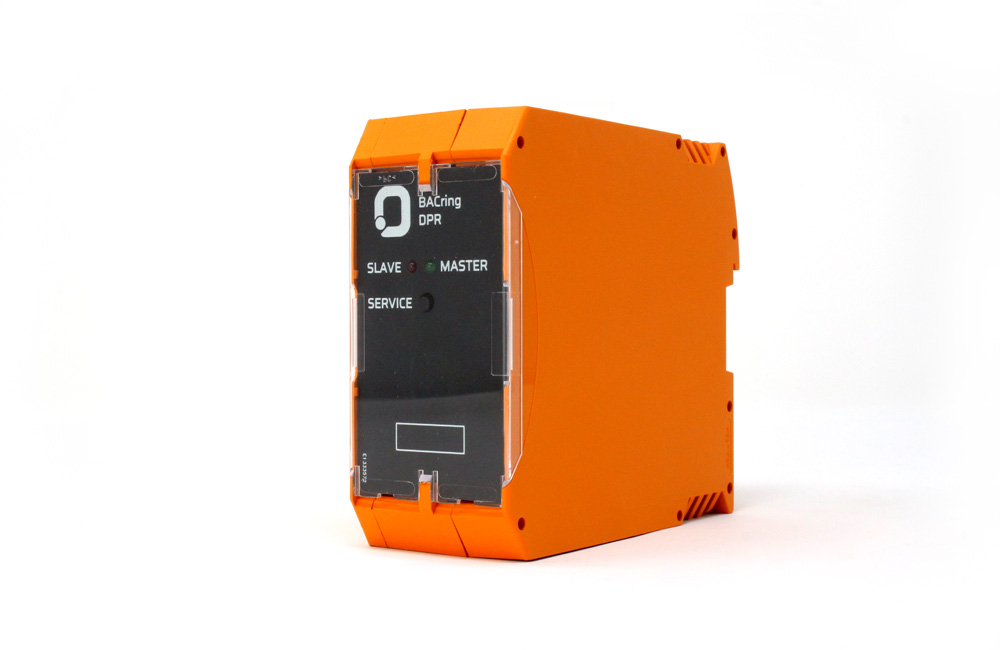
Product images

Connection diagram

Further information

Power supply
+18 - 27V DC, max. 2W
Display
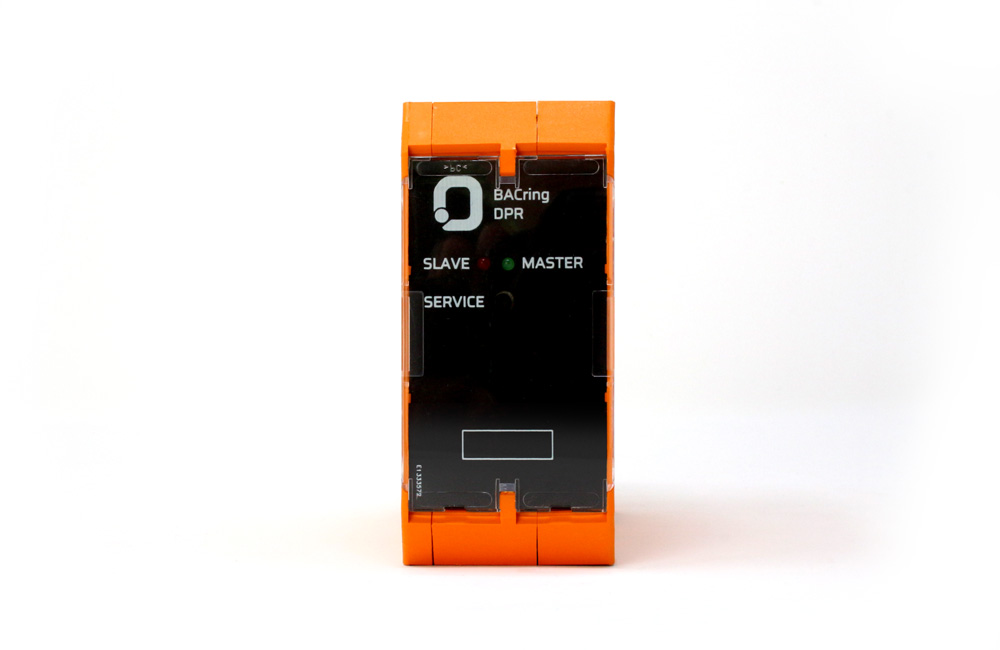
DPC-RP green LED / DPC-RS red LED
Controls
  • Service button (No function)
Switchover times
Switchover times according to the logic (see table)
Connections
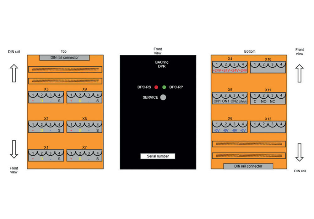
  • 6 x 4-pin bus connector Phoenix Contact FKCT-2.5/4-ST-KMGY (4-pin, female)
  • 4 x 4-pin 24V power connector Phoenix Contact FKCT-2.5/4-ST-KMGY (4-pin, female)
  • 1 x 4-pin error relay Phoenix Contact FKCT-2.5/4-ST-KMGY (4-pin, female)
  • 1 x 4-pin control signal connector Phoenix Contact FKCT-2.5/4-ST-KMGY (4-pin, female)
EMC conformity
  • 2014/35/EU, EN61000-6-1, EN61000-6-3, EN61000-4-2..-5
Maintenance
Maintenance-free
Assembly
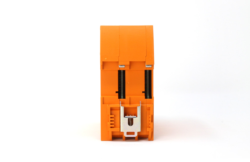
DIN rail mounting
Temperature
0° to +50°C
Air humidity
  • Stored: 0% - 80%, non-condensing
  • Operation: 0% - 70%, non-condensing
Safety class
IP 20
Dimensions (W x H x D)
46 x 114 x 120 mm
Housing
Phoenix ME MAX (orange)
Weight
Approx. 0.3 kg
Download PDF Datasheet